Square or cross-section of the conductor - the calculation formula. Square or cross-section of the conductor - formula for calculating the transverse cross section of the conductor
When the charged particles move the electrical charge from one place to another. However, if the charged particles make a disorderly thermal movement, such as free electrons in the metal, then the charge transfer will not be (Fig. 143). The electrical charge moves through the conductor cross section only if the electrons along with chaotic movement are involved in an ordered movement (Fig. 144). In this case, it is said that an electric current is installed in the conductor.
From the course of the class physics VII, you know that an ordered (directed) movement of charged particles is called electric shock. Electric current occurs with the ordered movement of free electrons in metal or ions in electrolytes.
However, if you move the neutral body as a whole, then, despite the ordered movement of a huge number of electrons and atomic nuclei, the electric current does not occur. A full charge carried through any conductor cross-section will be zero at the same time, since the charges of different signs are moved at the same average speed. The current in the conductor will occur only if when the charges move in one direction a positive charge carried through a section is not equal to a negative module.
Electric current has a specific direction. For the direction of current takes the direction of movement of positively charged particles. If the current is formed by the movement of negatively charged particles, then the direction of the current is considered to be the opposite direction of movement of particles.
Current actions. The movement of particles in the conductor we are not directly observed. However, the existence of an electric current can be judged by the actions or phenomena that it is accompanied.
First, the conductor through which the current flows is heated.
Secondly, the electric current can change the chemical composition of the conductor, for example, to highlight its chemical components (copper from the solution of copper mosquap, etc.). This kind
processes are observed not in all conductors, but only in solutions (or melts) of electrolytes.
Thirdly, the current has a magnetic effect. So, a magnetic arrow near the conductor turns to the current. The magnetic effect of the current is unlike the chemical and thermal, as it is manifested by everyone without exception. The chemical effect of the current is observed only in electrolytes, and the heating is absent from superconductors (see § 60).
Current power. If an electric current is installed in the circuit, then this means that an electrical charge is transferred through the cross-section of the conductor all the time. The charge transferred per unit of time serves as the main quantitative characteristic of the current called the power of the current. If the conductor is charged through the transverse cross section of the conductor during the time:
Thus, the current strength is equal to the ratio of the charge portable through the cross section of the conductor over the time interval at this time interval. If the current current does not change over time, the current is called constant.
The strength of the current, like the charging, is a scalar value. It can be both positive and negative. The current of the current depends on which directions along the conductor to take for positive. The strength of the current if the direction of the current of the coincide gives with a conditionally selected positive direction along the conductor. Otherwise
The strength of the current depends on the charge carried by each particle, the concentration of particles, the speed of their directional movement and the cross-sectional area of \u200b\u200bthe conductor. Show it.

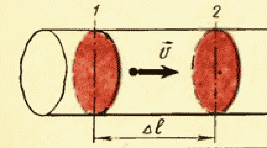
Let the conductor have a cross section of 5. For a positive direction in the conductor, we take direction from left to right. The charge of each particle is equal. In the volume of the conductor, limited by sections and 2, contains particles, where - the concentration of particles (Fig. 145). Their overall charge If the particles move on from left to right at an average speed, then during all particles prisoners in the volume under consideration, will pass through the section 2. Therefore, the current is equal.
Electric current has a power? Yes, imagine ... Why do I need power? Well, for what, in order to make a useful work, and it is not useful :-), the main thing is to do something. Our body also has strength. Someone has a force such that can one blow to the brick in the fluff and the dust, the other will not even be able to raise the spoon :-). So, dear my readers, electric current also has a power.
Imagine a hose with which you water your garden.
Low Slang is a wire, and the water in it is an electric current. We slightly opened the crane and the water ran along the hose. Slowly, but all the same ran. The strength of the jet is very weak. We will not even be able to pour someone from the hose with such a jet. Now open the crane on the full coil! And we have such a jet that is even enough to pour and the neighboring section :-).
Now imagine that you fill the bucket. Do you fill it firmly from the hose or from the Kranka? The diameter of the hose and the crane is equal


Of course, pressure from the yellow hose! But why is it going on? The fact is that the volume of water for an equal period of time from the crane and yellow hose is also different. Or in other words, from the hose, the number of water molecules will run away much more than the crane for the same time.
With wires exactly the same story). That is, for an equal period of time, the number of electrons running over the wire can be completely different. Now you can define the strength of the current.
So, the strength of the current is the number of electrons passing through the cross-sectional area of \u200b\u200bthe conductor per unit of time, well, let's say, per second. Below in the figure is shaded with green lines, this area of \u200b\u200bthe cross section of the wire through which the electric current runs.

- for direct current -
where I is the power of DC;
- for non-permanent current - in two ways:
1) by the formula -
Q \u003d \u003ci\u003e Δ t,
where \u003ci\u003e is the average strength of the current;
2) graphically - as an area of \u200b\u200bcurvilinear trapezium (Fig. 8.1).
In the international system units, the charge is measured in the coulons (1 CL).
The strength of the current is determined by the speed, concentration and charge of current carriers, as well as the cross-sectional area of \u200b\u200bthe conductor:
where q is the charge carrier charge module (if electrons are electrons, then q \u003d 1.6 ⋅ 10 -19 CL); n is the concentration of current carriers, n \u003d \u003d n / v; N is the number of current carriers passing through a cross-section of the conductor (located perpendicular to the speed of movement of the current carriers) during Δt, or the number of current carriers in the volume V \u003d SV ΔT (Fig. 8.2); S is the cross-sectional area of \u200b\u200bthe conductor; V is the speed of the speed of the current carrier.

The current density is determined by the current force passing through the unit of the cross section of the conductor, located perpendicular to the current direction:
where I is the current strength; S is the cross-sectional area of \u200b\u200bthe conductor (located perpendicular to the speed of movement of current carriers).
Current density is vector magnitude.
The direction of density of the current j → coincides with the direction of the speed of motion of positive carriers of the current:
j → \u003d Q n v →,
where q is the charge carrier charge module (if electrons are electrons, then q \u003d 1.6 ⋅ 10 -19 CL); V → - the speed of movement of current carriers; n is the concentration of current carriers, n \u003d n / v; N is the number of current carriers passing through a cross-section of the conductor (located perpendicular to the speed of movement of the current carriers) during Δt, or the number of current carriers in the volume V \u003d SV ΔT (Fig. 8.2); V is the speed of the speed of the current carrier; S is the cross-sectional area of \u200b\u200bthe conductor.
In the international system of units, the current density is measured in amperes divided into a square meter (1 A / m 2).
The power of the current in the gases (electric current in the gases is caused by the movement of ions) is determined by the formula
I \u003d n t ⋅ | Q | .
where N / T is the number of ions that pass through the transverse section of the vessel every second (every second); | Q | - Ion Charge Module:
- for a simple ion -
| Q | \u003d 1.6 ⋅ 10 -19 CL,
- for two-chain ion -
| Q | \u003d 3.2 ⋅ 10 -19 CL
Example 1. The number of free electrons in 1.0 m 3 of copper is 1.0 ⋅ 10 28. Find the speed of the directional electron movement in the copper wire with a cross-sectional area of \u200b\u200b4.0 mm 2, which flows 32 A.
Decision. The rate of directional movement of current carriers (electrons) is associated with the current in the conductor of the formula
where q is the charge carrier charge module (electron); n is the concentration of current carriers; S is the cross-sectional area of \u200b\u200bthe conductor; V is the speed of the directional movement of current carriers in the conductor.
Express this formula from this formula - the speed of current carriers -
v \u003d i Q n s.
To calculate the speed, we use the following values \u200b\u200bof the values \u200b\u200bincluded in the formula:
- the value of the current strength and the cross-sectional area of \u200b\u200bthe conductor are given in the condition of the problem: I \u003d 32 A, S \u003d 4.0 mm 2 \u003d 4.0 ⋅ 10 -6 m 2;
- the value of the elementary charge (equal to the electron charge module) is a fundamental constant (constant value): Q \u003d 1.6 ⋅ 10 -19 CL;
- the concentration of current carriers - the number of current carriers in a unit of conductor volume -
n \u003d n v \u003d 1.0 ⋅ 10 28 1 \u003d 1.0 ⋅ 10 28 m -3.
Calculate:
v \u003d 32 1.6 ⋅ 10 - 19 ⋅ 1.0 ⋅ 10 28 ⋅ 4.0 ⋅ 10 - 6 \u003d 5.0 ⋅ 10 - 3 m / s \u003d 5.0 mm / s.
The speed of the directional electron movement in the specified conductor is 5.0 mm / s.
Example 2. The current of the current in the conductor evenly increases from 10 to 12 and for 12 s. Which charge passes through the cross section of the conductor during the specified time interval?
Decision. The strength of the current in the conductor varies over time. Therefore, the charge transferred by the current carriers through a cross-section of the conductor, located perpendicular to the speed of the current carriers, for some period of time, can be calculated in two ways.
1. The desired charge can be calculated using the formula
Q \u003d \u003ci\u003e Δ t,
where \u003ci\u003e is the average strength of the current; ΔT - time interval, Δt \u003d 12 s.
The strength of the current increases in the conductor uniformly; Consequently, the average current is determined by the expression
\u003cI\u003e \u003d i 1 + i 2 2,
where i 1 is the value of the current value at the initial moment of time, i 1 \u003d 10 A; I 2 - the value of the current value in the end point in time, i 2 \u003d 12 A.
Substitting the expression of the average current in the formula for calculating the charge, we get
Q \u003d (i 1 + i 2) Δ T 2.
Calculation gives value
Q \u003d (10 + 12) ⋅ 12 2 \u003d 132 CL \u003d 0.13 CCL.
The figure shows the dependence I (T) specified in the condition problem.

The charge transferred by the conductor carriers through the cross section of the conductor, located perpendicular to the speed of the current carriers, during the specified period of time, is numerically equal to the area of \u200b\u200bthe trapezoid, limited to four lines:
- straight line I (t);
- perpendicular to the time axis restored from point T 1;
- perpendicular to the time axis restored from point T 2;
- time T.
The calculation will be produced by the Formula of the Spring Square:
Q \u003d 12 + 10 2 ⋅ 12 \u003d 132 CL \u003d 0.13 CCL.
Both methods for calculating the charge transferred by the current speakers during the specified period of time give the same result.
To the submission of electric current can be approached from different positions. One of them is macroscopic, the other is based on the analysis of the conduction mechanism. For example, the flow of pipe fluid can be considered as a continuous movement of the substance, but it can be analyzed and from the point of view of the movement of the particles of the liquid.
The first idea of \u200b\u200bthe electric current originated at the stage of the development of physics, when the conductivity mechanism has not yet been known. It was then that a physical value arose - tok Power which shows which electrical charge passes through the cross section of the conductor per unit of time. Current power. Unit of current - amp (a) :.
From the determination of the current strength, two features of this value are followed. One of them is the independence of current force from the cross section of the conductor, according to which the current flows. The second is the independence of the current force from the spatial location of the chain elements, in which you have repeatedly could make sure that no matter how the conductors moved, it does not affect the current strength. Current is called constantIf the current current does not change over time.
Thus, an idea of \u200b\u200belectric current, its strength appeared when it was not yet clear what it is.
The study of the electrical conductivity of various substances has shown that in different substances, various charged free particles move under the action of the electric field during the current flow. For example, in metals - these are electrons, in liquids are positive and negative ions, in semiconductors - electrons and "holes". Not only the types of particles, but also the nature of their interaction with the substance in which there is current. Thus, free electrons in metals are moving freely between the nodes of the crystal lattice, then faced with ions located in the nodes. In electrolytes, the ions interact with each other and with fluid atoms.
But for all substances there: particles in the absence of the field are moving chaotic, in the occurrence of the field to the rate of chaotic movement, a very small amount of the velocity is added or in the direction of the field (for positive particles), or in the opposite field (for negative particles). This additional speed is called drift speed . The average rate of chaotic movement is hundreds of meters per second, drift speed - several millimeters per second. However, it is this small additive that explains all the actions of the current.
For any substances, it is possible to obtain a formula for calculating the current: ![]() , where - the concentration of charged particles is the charge of one particle, the cross-sectional area.
, where - the concentration of charged particles is the charge of one particle, the cross-sectional area.
In this way, electricity - This is an ordered movement of charged particles.
It may seem that this formula is contrary to the statement of the independence of the current force from the cross-sectional area of \u200b\u200bthe conductor. But this independence is an experimental fact. It is possible to explain it by the fact that the drift speed is larger there, where the cross section is smaller, and through a greater section of the particle drift slower.
An experienced fact is that when applied to the conductor permanent Potential differences on it goes d.C.. This fact contradicts, at first glance, the formula ![]() . Indeed, with a constant potential difference in the substance, a field with a constant field strength is created. Consequently, the free particles acts constant strength and their speed should increase. It turns out that with constant voltage, the current strength should increase in proportion to time. This does not occur because when current flows in the substance arises electrical resistance. It is it that ensures the constancy of the strength of the current at a constant potential difference.
. Indeed, with a constant potential difference in the substance, a field with a constant field strength is created. Consequently, the free particles acts constant strength and their speed should increase. It turns out that with constant voltage, the current strength should increase in proportion to time. This does not occur because when current flows in the substance arises electrical resistance. It is it that ensures the constancy of the strength of the current at a constant potential difference.
To measure the resistance, it is necessary to investigate the dependence of the current for the voltage. Chart of such a dependency is called vol - tamper characteristic. Three types of volt-ampere characteristics are possible (Fig. 40).
The classification of any electrical wires includes the basic parameters represented by conductivity, cross-sectional area or diameter, materials from which a conductor is made, typical features of insulating protection, flexibility level, as well as thermal resistance indicators.
The area or cross-section of the conductor is one of the most important criteria for choosing a wire.
The most widespread use of wire pHP and PUGHP wires, as well as runways, PHCB and PKGM, which have the following, very important to obtain a secure connection with the main technical characteristics:
- PUNP - Flat wired product of the installation or so-called mounting type, with single-robes of copper in PVC isolation. Such a kind is characterized by the amount of lived, as well as rated voltage in the range of 250 V with a frequency of 50 Hz and the temperature operating mode from minus 15 ° C to plus 50 ° C;
- PugNP - Flexible variety with multi-breeding veins. The main indicators that are represented by a rated voltage rate, frequency and temperature operating mode are not different from similar PHP data;
- APB. - Aluminum single-core variation, a round wire having a protective PVC isolation and a single-rocker or a multi-breeding core. The difference of this species is the resistance to damage to mechanical type, vibrations and chemical compounds. The temperature operational mode is from minus 50 ° C to plus 70 ° C;
- PBC. - a multicore copper variety with PBX-insulation that gives the wire high density indicators and a traditional rounded form. The heat-resistant lived is calculated for the nominal level 380 V at a frequency of 50 Hz;
- PKGM. - Power assembly variety represented by a single-core copper wire with silicone rubber or fiberglass insulation, impregnated with heat-resistant composition. The temperature operational mode is from minus 60 ° C to plus 180 ° C;
- PHCB. - Heating single-core variety in the form of a single-wire wire based on galvanized or blond steel. The temperature operational mode ranges from minus 50 ° C to plus 80 ° C;
- Runway - Single-core copper variety with multi-breed residential and insulation based on PBX or polyethylene. The temperature operational mode ranges from minus 40 ° C to plus 80 ° C.
In conditions of low power, a Copper Wire of the SCBP with protective external PBX-insulation is used. A multi-voltage type has excellent flexibility indicators, and the wired product itself is calculated by a maximum of 380 V, at a frequency in the range of 50 Hz.
Wired products of the most common types are implemented in bays, and most often have white insulation staining.
Cross section area
In recent years, there has been a noticeable decrease in the qualitative characteristics of the manufactured cable products, as a result of which the resistance indicators suffer - the cross-section of the wires. The diameter of any conductor must necessarily have compliance with all the parameters declared by the manufacturer.
Any deviation that makes up even 15-20% may cause significant overheating of electrical wiring or melting the insulating material, so the selection of the area or thickness of the conductor should be paid to high attention not only in practice, but also from the point of view of the theory.

Cross section of conductors
The parameters most important for the correct sequence sequence are reflected in the following recommendations:
- the thickness of the conductor is sufficient for the unimpeded passage of electric flow, with the highest possible heating of the wire within 60 ° C;
- the conductor cross section is sufficient for a sharp decrease in voltage that does not exceed the permissible indicators, which is especially important for very long wiring and significant currents.
Special attention is required to be given to the maximum indicators of the working temperature regime, when the conductor and protective insulation are exceeded.
The cross section of the conducted conductor and its protective insulation should necessarily provide a complete mechanical strength and reliability of electrical wiring.
Cross-section Formula
As a rule, wires have a circular cross section, but permissible current indicators should be calculated according to the cross-sectional area. In order to independently define the cross-sectional area in a single-core or multi-core wire, the shell is carefully opened, which is insulation, after which the diameter is measured in a single-core conductor.
The area is determined in accordance with the physical formula well known to schoolchildren:
S \u003d π x d² / 4 or s \u003d 0.8 x d², where:
- S is an area of \u200b\u200bcross section in mm 2;
- π - the number π, the standard value equal to 3.14;
- D is a diameter in mm.

Conductor
Measurements of the stranded wire will require its preliminary dissipation, as well as the subsequent calculation of the number of all veins inside the beam. Then the diameter of one component of the element is then measured and the cross-sectional area is calculated in accordance with the standard formula indicated above. At the final stage of measurements, residential areas are summed up in order to determine the indicators of their common cross section.
In order to determine the diameter of the wired vein, a micrometer or a caliper is used, but if necessary, you can use the standard student line or centimeter. The measured vest of the wire must be as close as possible to the wand on two dozens of turns. Using a ruler or centimeter, it is required to measure the winding distance in mm, after which the indicators are used in the formula:
D \u003d L / N,
- l is presented by the distance of the veil winding in mm;
- n is the number of turns.
It should be noted that the larger cross section of the wire allows to provide a margin in current indicators, as a result of which the level of electrical wiring load can be slightly exceeded.
To independently determine the wired cross section of the monolithic core, is required by a conventional caliper or micrometer, measure the diameter of the inside of the cable without protective insulation.
Table matching the diameters of the wires and the area of \u200b\u200btheir cross section
The definition of a cable or wired cross section according to the standard physical formula is among sufficiently time-consuming and complex processes that do not guarantee the obtaining maximum efficiency, therefore it is advisable to use specially special table data for this purpose.
| Cable cable diameter | Cross-section indicators | Conductors with a residential copper type | ||
| Power in the network of 220 V | Current | Power under network 380 in | ||
| 1,12 mm | 1.0 mm 2. | 3.0 kW | 14 A. | 5.3 kW |
| 1.38 mm | 1.5 mm 2. | 3.3 kW | 15 A. | 5.7 kW |
| 1.59 mm | 2.0 mm 2. | 4.1 kW | 19 A. | 7.2 kW |
| 1.78 mm | 2.5 mm 2. | 4.6 kW | 21 A. | 7.9 kW |
| 2.26 mm | 4.0 mm 2. | 5.9 kW | 27 A. | 10.0 kW |
| 2.76 mm | 6.0 mm 2. | 7.7 kW | 34 A. | 12.0 kW |
| 3.57 mm | 10.0 mm 2. | 11.0 kW | 50 A. | 19.0 kW |
| 4.51 mm | 16.0 mm 2. | 17.0 kW | 80 A. | 30.0 kW |
| 5.64 mm | 25.0 mm 2. | 22.0 kW | 100 A. | 38.0 kW |
| 6.68 mm | 35.0 mm 2. | 29.0 kW | 135 A. | 51.0 kW |
How to determine the cross section of a stranded wire?
Strategic wires are also known as multi-breed or flexible cables, which are tightly retained in one bundle of single-core type wires.To independently correctly make the calculation of the section or the area of \u200b\u200bmulticore wires, it is necessary to initially calculate the cross section of each wire in the beam, after which the result obtained multiplies them to their total number.
"Conductors and dielectrics" - electrical characteristics of the medium are determined by the mobility of charged particles in it. Dielectrics. Free charges - charged particles of one sign capable of moving under the action of an electric field. Dielectrics - gases, distilled water, benzene, oil, porcelain, glass, mica and others. External electric field.
"Golden section" - the Pokrovsky Cathedral (the Church of Vasily Blessed). Admiralty. The Intercession of the Virgin on Nerli. Picture in the lobby of the second floor. Research tasks: Golden section - proportion. St Basil's Church. The purpose of the study: to withdraw the law of beauty of the world from the point of view of mathematics. Golden cross section in architecture. Completed the student of the 10th grade of Saint Yulia.
"Sections of the parallelepiped" - 1. The introductory word of the teacher - 3 min. 2. Activation of knowledge of students. Rectangle CKK'C '- cross section ABCDA'B'C'D'. Homework. The sequential plane crosses the edges by cuts. ? Mnk- section parallelepiped ABCDA'B'C'D '. Task: Build a section through the edge of parallelepiped and point K. Self-work of students.
"The proportions of the golden section" - dividing the segment "golden cross section". "Golden Pentagon". Euclid, Leonardo da Vinci, Luka Pacheti. "Golden Rectangle". Inanimate nature. For example, the ratio of sushi and water on the surface of the Earth are in the golden proportion. In numbers, the harmony of the universe is founded. "Golden section" in nature, art and architecture.
"Construction of sections" - if the cross section is made, then the open line is carried out, two thickened strokes. Designation of sections. Some parts of the part elements are more convenient to show in sections. Sections in the drawings are divided into rendered and superimposed. Sections are performed on the same scale as the image to which it applies.
"Explorer in the electrical circuit" - solve the task. Conductor connection. Consissessing light bulbs in the Christmas Garland. Determine the resistance of the chain resistance of each resistor is 3 ohms. 1. Two conductor resistance to 4 ohms and 2 ohms are connected sequentially. Sequential compound i \u003d i1 \u003d i2 u \u003d u1 + u2 r \u003d R1 + R2 for identical conductors R \u003d NR1.
Copper conductor has a length of 500 m and a cross-sectional area of \u200b\u200b0.5 mm2. A) What is the current power in the conductor at a voltage at its ends of 12V? The resistivity of the copper 1.7 multiply 10 -8 the degrees of OM multiplied to m b) determine the rate of an ordered electron movement. The concentration of free movement for copper equal to 8.5 multiply by 10 V 28 degrees of meters per minus 3 degrees, and an electron charge module is 1.6 multiply by 10 per minus 19 degrees of CL B) to the first conductor consistently connected the second copper conductor twice the larger diameter. . What will be the speed of an ordered electron movement in the second conductor?
Solution for question a)
What do we know about current, voltage and resistance?
I \u003d u / r, u \u003d i * r
I - current in amperes,
U - Volt Tension
R - resistance in Omah
What is a current of 1 ampere?
This is such a current at which in 1 second through the conductor takes place in 1 pendant.
1 A \u003d 1 CL / s (1 amp is 1 pendant per second)
What do we know from the conditions?
U \u003d 12 V - Voltage
p \u003d 1.7 * 10E-8 Ohm * M is the resistivity "PO" (the value of the conductor resistance by cross section 1 square meter and 1 meter length).
Our conductor has a cross section S \u003d 0.5 mm ^ 2 or 0.0000005 m ^ 2 or 0.5 * 10E-6 m ^ 2 (in one square. Meter 10,000 square meters. Millimeters - 1000 * 1000) and length L \u003d 500m
We get the resistance of the conductor
R \u003d P * L / S\u003d 1.7 * 10E-8 * 500 / 0.5 * 10E-6 \u003d 0.000000017 * 500 / 0.0000005 \u003d 17 ohm
The current will then be:
I \u003d u / r\u003d 12/17 A (0.706. AMPER)
Solution for Question b)
The strength of the current I is as expressed in the following values:
I \u003d e * n * s * vc
e - Electron Charge, CL
n - electrons concentration, pcs / m ^ 3 (pieces per cubic meter)
S - cross section area, m ^ 2
VSR - average rate of ordered electron movement, m / s
therefore
VSR \u003d I / (E * N * S)\u003d (12/17) / (1.6 * 10E-19 * 8.5 * 10E + 28 * 0.5 * 10E-6) \u003d 11,657 * 10E-3 m / s (or 11,657 mm / s)
Solution for Question B)
We argue similarly to the decision A) and b)
First you need to find a total current (general resistance).
T. K. In the condition B) the diameter is referred to, we conclude that all the wires of the circular cross section.
The length of the second wire is not specified. Suppose it is also 500m.
The area of \u200b\u200bthe circle is determined by the ratio:
S \u003d (PI * D ^ 2) / 4,
where D is the diameter of the circle,
pi \u003d 3,1415926.
Thus, with an increase in the diameter have, the area of \u200b\u200bthe wire cross section increases in four,
with an increase in the diameter, three times, the cross-sectional area of \u200b\u200bthe wire increases nine times and so on.
TOTAL S2 \u003d S1 * 4 \u003d 0.5 * 10E-6 * 4 \u003d 2 * 10E-6 m ^ 2
If the cross-sectional area has increased fourwise, then, with the same length, its resistance will decrease in four.
TOTAL R2 \u003d R1 / 4 \u003d 17/4 ohms \u003d 4.25 ohms
General resistance with a serial connection is summed, so
I \u003d u / r \u003d u / (R1 + R2)\u003d 12 / (17 + 17/4) \u003d 48/85 \u003d 0.5647. A.
An ordered electron speed for the second conductor will then be:
VSR \u003d I / (E * N * S2) \u003d (48/85) / (1.6 * 10E-19 * 8.5 * 10E + 28 * 2 * 10E-6) \u003d 0.02076 * 10E-3 m / s (or 0.02076 mm / s)
Tok Power
(if a ).
Cone density
where S.- Cross-section area of \u200b\u200bthe conductor.
Current density in the conductor
where -good the ordered movement of charges in the conductor, n.- the concentration of charges, e.- elementary charge.
The dependence of resistance from the parameters of the conductor
where l.- the length of the conductor, S.- The cross-sectional area of \u200b\u200bthe conductor is the resistivity - the specific conductivity.
Dependence of temperature resistivity
![]() ,
,
where is the temperature coefficient of resistance, the resistance at.
Resistance with sequential (A) and parallel (b) connection of conductors
where is the resistance of the conductor n. - The number of conductors.
Ohm's law:
for a homogeneous section of the chain
![]() ,
,
for an inhomogeneous section of the chain
![]() ,
,
for closed chain
where U.- voltage on a homogeneous section of the chain, - the potential difference at the ends of the chain section, - the source EMF, r.- Internal resistance of the current source.
Short circuit current
Current operation for time t.
Current power
Joule-Lenza law (the amount of heat released during current passing through the conductor)
Power source current
The efficiency of the current source
 .
.
Kirchhoff rules
1) - for nodes;
2) ![]() - for contours,
- for contours,
where - the algebraic amount of current forces converging in the node is the algebraic amount of EDC in the circuit.
2.1.
At the ends of the copper wire with a length of 5 m, a voltage of 1 V is maintained to determine the current density in the wire (resistivity of copper ![]() ).
).
BUT. ![]() B.
B. ![]()
S. D. ![]()
2.2. Resistor resistance 5 ohms, voltmeter and current source are connected in parallel. The voltmeter shows the voltage of 10 V. If you replace the resistor to another with a resistance of 12 ohms, then the voltmeter will show the voltage 12 V. Determine the EMF and the internal resistance of the current source. Current through a voltmeter neglected.
A. B.
S. D.
2.3. Determine the current strength in the chain consisting of two elements with EDC, equal to 1.6 V and 1.2 V and internal resistances of 0.6 ohms and 0.4 ohms, respectively, connected by the eponymous poles.
A. B. C. D.
2.4. The galvanic element gives an external resistance of 0.5 ohm current of 0.2 A. if the external resistance is replaced by 0.8 ohms, then the current in the circuit 0.15 A. Determine the short circuit current.
A. B. S. D.
2.5. The current source with EDC 12 in the load is connected. Voltage at the terminals of the source 8 V. Determine the CPD of the current source.
A. B. S. D.
2.6. The external circuit of the current source consumes the power of 0.75 W. Determine the current strength in the circuit if the EDC of the 2B source and the internal resistance of 1 ohm.
A. V. S. D.
2.7. The current source with EDC 12 V and the internal resistance of 1 ohms is connected to the load of 9 ohm. Find: 1) Current strength in chains, 2) Power released in the outer part of the chain, 3) Power lost in the current source, 4) Complete power of the current source, 5) CPD source.
2.8. The winding of the electric boiler has two sections. If one section is included, water boils after 10 minutes, if the other, then after 20 minutes. After how many minutes, water boils if both sections include: a) sequentially; b) in parallel? The voltage on the clips of the boiler and the efficiency of the installation is considered the same in all cases.
A. [a) 30 min, b) 6.67 min] V. [a) 6.67 min; b) 30 min]
S. [a) 10 min; b) 20 min] D. [a) 20 min; b) 10 min]
2.9. A ammeter resistance 0.18 ohms is designed to measure the current for up to 10 A. What resistance must be taken and how to turn it on so that the current can be measured to 100 Ahmremmer?
A.V.
S. D.
2.10. Voltmeter resistance 2000 Ohms is designed to measure voltage up to 30 V. What resistance must be taken and how to enable it so that this voltmeter can be measured voltage up to 75 V?
A.V.
S. D.
2.11 . * The current in the conductor resistance 100 ohms is evenly increasing from 0 to 10 A for 30 s. What is the amount of heat that highlighted during this time in the conductor?
A. V. S. D.
2.12.* The current in the conductor resistance 12 ohms evenly decreases from 5 a to 0 for 10 s. What amount of heat is highlighted in the conductor during this time?
A. V. S. D.
2.13.* According to the conductor, the resistance of 3 ohms flows evenly increasing current. The amount of heat released in the conductor for 8 s is equal to 200 J. Define the charge proceeding during this time by conductor. At the initial moment of time, the current was zero.
A. V. S. D.
2.14.* The current in the conductor resistance is 15 ohms evenly increases from 0 to some maximum for 5 s. During this time, the amount of heat of 10 kJ was released in the conductor. Find the average current value in the explorer over this time.
A. V. S. D.
2.15.* The current in the conductor evenly increases from 0 to some maximum value for 10 s. During this time, the amount of 1 kJ heat change was released in the conductor. Determine the rate of current increase in the conductor, if its resistance is 3 ohms.
A. V. S. D.
2.16. In fig. 2.1 \u003d \u003d, R 1 \u003d 48 Ohm, R 2 \u003d 24 Ohms, the voltage drop U 2 on the resistance R 2 is 12 V. Neglecting the inner resistance of the elements, determine the current strength in all parts of the chain and the resistance R 3.
 |
|
Fig. 2.1 Fig. 2.2 Fig. 2.3.
2.17. In fig. 2.2 \u003d 2B, R 1 \u003d 60 Ohm, R 2 \u003d 40 Ohm, R 3 \u003d R 4 \u003d 20 Ohm, R g \u003d 100 ohms. Determine the current strength I G through the galvanometer.
2.18. Find current strength in separate branches of Whitstone's bridge (Fig. 2.2), provided that the current flowing through the galvanometer is zero. EMF Source 2B, R 1 \u003d 30 Ohm, R 2 \u003d 45 Ohm, R 3 \u003d 200 Ohm. Internal source resistance to neglect.
2.19. In fig. 2.3 \u003d 10 V, \u003d 20 V, \u003d 40 V, and resistance R 1 \u003d R 2 \u003d R 3 \u003d 10 ohms. Determine the strength of currents through resistance ( I.) And through sources (). Internal resistance to sources neglected. [ I. 1 \u003d 1A, I. 2 \u003d 3A, I. 3 \u003d 2a, \u003d 2a, \u003d 0, \u003d 3a]
2.20. In fig. 2.4 \u003d 2.1 V, \u003d 1.9 V, R 1 \u003d 45 Ohm, R 2 \u003d 10 Ohm, R 3 \u003d 10 ohms. Find current strength in all parts of the chain. Internal resistance of elements neglected.

Fig. 2.4 Fig. 2.5 Fig. 2.6.
2.21. In fig. 2.5 The resistance of the voltmeters is equal to R 1 \u003d 3000 Ohm and R 2 \u003d 2000 Ohms; R 3 \u003d 3000 Ohm, R 4 \u003d 2000 Ohm; \u003d 200 V. Find the testimony of voltmeters in cases: a) key TO open, b) key TO Closed. Internal source resistance to neglect. [a) u 1 \u003d 120 V, u 2 \u003d 80 V, b) u 1 \u003d u 2 \u003d 100 V]
2.22. In fig. 2.6 \u003d 1.5 V, internal resistances of sources R 1 \u003d R 2 \u003d 0.5 Ohm, R 1 \u003d R 2 \u003d 2 Ohm, R 3 \u003d 1 Ohm. Resistance milliammeter 3 ohms. Find a reference to a milliammeter.
 2.23.
In fig. 2.7 \u003d 110 V, R 1 \u003d R 2 \u003d 200 Ohm, the resistance of the voltmeter 1000 V. Find the testimony of the voltmeter. Internal resistance to sources neglected.
2.23.
In fig. 2.7 \u003d 110 V, R 1 \u003d R 2 \u003d 200 Ohm, the resistance of the voltmeter 1000 V. Find the testimony of the voltmeter. Internal resistance to sources neglected.
Fig. 2.7 Fig. 2.8 Fig. 2.9.
2.24. In fig. 2.8 \u003d \u003d 2B, the internal resistances of the sources are 0.5 Ohm, R 1 \u003d 0.5 Ohm, R 2 \u003d 1.5 Ohm. Find current strength in all parts of the chain.
2.25. In fig. 2.9 \u003d \u003d 100 V, R 1 \u003d 20 Ohm, R 2 \u003d 10 Ohm, R 3 \u003d 40 Ohm, R 4 \u003d 30 ohms. Find an ammeter reading. Internal resistance of sources and ammeter neglected.
2.26. What power is shifting an ammeter in fig. 2.10, the resistance of which R a \u003d 500 ohms, if \u003d 1 V, \u003d 2 V, R 3 \u003d 1500 Ohms and the voltage drop on the resistance R 2 is 1 V. internal resistance of sources neglected.
2.27. In fig. 2.11 \u003d 1.5 V, \u003d 1.6 V, R 1 \u003d 1 com, R 2 \u003d 2 com. Determine the testimony of the voltmeter if its resistance R v \u003d 2 com. Resistance to sources neglected.
 |
|||||||||
|
|||||||||
|
|||||||||
|
|||||||||
Fig. 2.10 Fig. 2.11 Fig. 2.12.
2.28. In fig. 2.12 Resistance R 1 \u003d 5Ω, R 2 \u003d 6 Ohm, R 3 \u003d 3 ohms. Find an ammeter reading if the voltmeter shows 2.1 V. Resistance to the source and ammeter to neglect.
2.29 . Determine the emf of the source in the scheme in Fig. 2.13, if the current current flowing through it is 0.9 A, the internal resistance of the source of 0.4 ohms. R 1 \u003d 30 Ohm, R 2 \u003d 24 Ohm, R 3 \u003d 50 Ohm, R 4 \u003d 40 Ohm, R 5 \u003d 60 ohms.
2.30. Find an ammeter reading in the diagram in Fig. 2.14, if EDC is equal to 19.8 V, the internal resistance is 0.4 ohms, R 1 \u003d 30 ohms, R 2 \u003d 24 Ohm, R 3 \u003d 50 ohms, R 4 \u003d 40 Ohm, R 5 \u003d 60 ohms.
 |
Fig. 2.13 Fig. 2.14 Fig. 2.15
2.31 . Find the values \u200b\u200bof all resistance in the diagram in Fig. 2.15, if a current of 0.4 μ is flowing through the resistance R 1, through the resistance R 2 current of 0.7 μA, through the resistance R 3 - 1.1 μA, through the resistance R 4 does not flow. Internal resistance of elements neglected. E 1 \u003d 1.5 V; E 2 \u003d 1.8 V.

Fig. 2.16 Fig. 2.17 Fig. 2.18
2.32. Determine E 1 and E 2 in the diagram in fig. 2.16, if R 1 \u003d R 4 \u003d 2 Ohm, R 2 \u003d R 3 \u003d 4 ohms. The current flowing through the resistance R 3 is 1A, and through the resistance R 2 current does not flow. Internal resistances of elements R 1 \u003d R 2 \u003d 0.5 Ohm.
2.33. Determine the current strength in all parts of the chain in the diagram in Fig. 2.17, if E 1 \u003d 11 V, E 2 \u003d 4 V, E 3 \u003d 6 V, R 1 \u003d 5 Ohm, R 2 \u003d 10 Ohm, R 3 \u003d 2 ohms. Internal resistances of sources R 1 \u003d R 2 \u003d R 3 \u003d 0.5 Ohm.
2.34. In the diagram in fig. 2.18 R 1 \u003d 1 Ohm, R 2 \u003d 2 Ohm, R 3 \u003d 3 Ohm, the current strength through the source is 2a, the potential difference between points 1 and 2 Equal to 2 V. Find the resistance R 4.
Elektomagnetism
Basic formulas
Magnetic induction is associated with magnetic field strength by the ratio
where ![]() - magnetic constant,
- magnetic constant,
Magnetic permeability of isotropic medium.
The principle of superposition of magnetic fields
where is the magnetic induction created by each current or moving charge separately.
Magnetic field induction, created by an infinitely long straight conductor with a current,
where - the distance from the conductor with the current to the point in which the magnetic induction is determined.
Magnetic induction of a field created by a straight-line conductor with a current terminal
![]() ,
,
where - the angles between the current element and the radius-vector conducted from the point under consideration to the ends of the conductor.
Magnetic field induction in the center of a circular conductor with current
where is the radius of a circular turn.
Magnetic field induction on the axis of the circular conductor with a current
 ,
,
where is the radius of the circular turn - the distance from the center of the turn to the point in which the magnetic induction is determined.
Magnetic field induction inside toroid and infinitely long solenoid
where is the number of turns per unit length of the solenoid (toroid).
Magnetic field induction on the axis of the end length solenoid
![]() ,
,
where - the angles between the coil axis and the radius-vector conducted from this point to the ends of the coil.
Ampere power acting on the conductor element with a current in a magnetic field,
where is the angle between the current directions and the magnetic induction of the field.
Magnetic moment circuit with shock
where is the contour area,
Unit vector normal (positive) to the contour plane.
The torque acting on the contour with the current placed in a homogeneous magnetic field,
![]() ,
,
where is the angle between the direction of normal to the circuit plane and the magnetic induction of the field.
The power of the interaction between two straight-line parallel conductor with currents and
![]() ,
,
where - the length of the conductor, is the distance between them.
Magnetic flow through the platform
where, is the angle between the direction of the magnetic induction vector and the normal to the site.
Magnetic stream of heterogeneous field through an arbitrary surface
where integration is conducted over the entire surface.
Magnetic stream of a homogeneous field through a flat surface
Operation of moving conductor with current in a magnetic field
where is the flow of magnetic induction, crossed by the conductor when it moves.
Lorentz power acting on a moving charged particle in a magnetic field,
where - the particle charge is the particle speed, the angle between the directions of the particle speed and the magnetic induction of the field.
E.D.S. induction
The difference of potentials at the ends of the conductor moving in a magnetic field,
where - the speed of movement of the conductor, the length of the conductor, is the angle between the direction of the speed of the conductor and the magnetic induction of the field.
E.D.S. self-induction
where is the inductance of the contour.
Solenoid inductance
![]() ,
,
where - the cross-sectional area of \u200b\u200bthe solenoid, the length of the solenoid, is the total number of turns.
Energy magnetic field circuit with current
Bulk energy density magnetic field
![]() .
.
 3.1.
In fig. 3.1 depicted a section of two straightforward infinitely long conductors with a current. The distance of the speaker between the conductors is 10 cm, I 1 \u003d 20 A, I 2 \u003d 30 A. Find the magnetic induction of the field caused by currents I 1 and I 2 at m 1, m 2 and m 3. Distances M 1 A \u003d 2 cm, AM 2 \u003d 4 cm and cm 3 \u003d 3 cm.
3.1.
In fig. 3.1 depicted a section of two straightforward infinitely long conductors with a current. The distance of the speaker between the conductors is 10 cm, I 1 \u003d 20 A, I 2 \u003d 30 A. Find the magnetic induction of the field caused by currents I 1 and I 2 at m 1, m 2 and m 3. Distances M 1 A \u003d 2 cm, AM 2 \u003d 4 cm and cm 3 \u003d 3 cm.
A.V.
S. D.
3.2. Solve the previous task, provided that currents flow in one
direction.
A.V.
S. D.
3.3. Two straight infinitely long conductor are perpendicular to each other and are in the same plane (Fig. 3.2). Find the magnetic induction of the field at points M 1 and m 2, if i 1 \u003d 2 A and I 2 \u003d 3 A. distances A am 1 \u003d AM 2 \u003d 1 cm, DM 1 \u003d cm 2 \u003d 2 cm.
 |  |
||
Fig. 3.2 Fig. 3.3.
A.V.
S. D.
3.4. Two straight infinitely long conductor are perpendicular to each other and are in mutually perpendicular planes (Fig. 3.3). Find the magnetic induction of the field at points M 1 and m 2, if i 1 \u003d 2 A and I 2 \u003d 3 A. distances A am 1 \u003d AM 2 \u003d 1 cm and ac \u003d 2 cm.
A.V.
S. D.
3.5. In fig. 3.4 depicted a cross section of three straightforward infinitely long conductors with a current. Distances as \u003d cd \u003d 5 cm; I 1 \u003d i 2 \u003d i; I 3 \u003d 2i. Find a point on a straight line AD, in which the induction of the magnetic field caused by currents I 1, I 2, I 3 is zero.
 |
A. B.
S. D.
3.6. Solve the previous task, provided that all currents flow in one direction.
A. B.
C. D.
3.7. Two circular turns with a radius of 4 cm each are located in parallel planes at a distance of 0.1 m from each other. Through the turns flow 2 \u003d i 2 \u003d 2 A. Find the magnetic induction of the field on the axis of the turns at the point that is equal to the distance from them. Toki in turns flow in one direction.
A. B. S. D.
3.8. Solve the previous task, provided that currents flow in opposite directions.
A. V. S. D.
3.9. The current in 2a flows along a long conductor, bent at an angle. Find the magnetic induction of the field at a point lying on the bisector of this angle and the sprinkle of the angle at a distance of 10 cm.
A. V. S. D.
3.10. On the conductor bent in the form of a rectangle with the parties but \u003d 8 cm and in \u003d 12 cm, flowing current I. \u003d 50 A. Determine the strength and magnetic induction of the field at the point of intersection of the diagonals of the rectangle.
A.V.
S. D.
3.11. On a wire frame having the form of a regular hexagon, flowing current I \u003d 2 A. In this case, the magnetic field B \u003d 41.4 mkl is formed in the center of the frame. Find the wire length from which the frame is made.
A. V. S. D.
3.12. According to the conductor, curved in the form of a circle flowing current. Magnetic field in the center of the circle B \u003d 6.28 mkl. Without changing current strength in the conductor, he was given the shape of a square. Determine the magnetic induction of the field at the point of intersection of the diagonals of this square.
A. V. D.
3.13. The solenoid winding contains two layers of tight-adjacent turns of the turns of the wire with a diameter d \u003d 0.2 mm. Determine the magnetic induction of the field on the axis of the solenoid, if the current flows the current i \u003d 0.5 A.
A. V. S. D.
3.14. A thin ring weighing 15 g and a radius of 12 cm carries a charge that is evenly distributed with a linear density of 10 nkl / m. The ring is evenly rotated with a frequency of 8 C -1 relative to the axis perpendicular to the ring plane and passing through its center. Determine the ratio of the magnetic moment of the circular current created by the ring, by its momentum of the pulse.
A. V. S. D.
3.15. Under two infinitely long direct parallel conductors, the distance between which is equal to 25 cm, flows current 20 and 30 A in opposite directions. Determine the magnetic induction of the field at a point removed at a distance of 30 cm from the first and 40 cm from the second conductor.
A. V. S. D. [27.0 MTL]
3.16. Determine the magnetic induction of the field on the axis of the thin wire ring with a radius of 10 cm, according to which the current 10 A, at a point located at a distance of 15 cm from the center of the ring.
A. V. S. D.
3.17. On a wire bent in the form of a square with a side of 60 cm, a constant current is flowing 3 A. to determine the magnetic induction of the field in the center of the square.
A. V. S. D.
3.18. The current, passing along a wire ring from a copper wire with a cross section of 1.0 mm 2, creates in the center of the ring magnetic induction of the field of 0.224 mT. The potential difference attached to the ends of the wire forming the ring is equal to 0.12 V. What current flows through the ring?
A. V. S. [2 A] D.
3.19. Current 2 A, flowing through a coil with a length of 30 cm, creates inside it the magnetic induction of the field of 8.38 mt. How many turns contains a coil? The diameter of the coil is considered small compared to its length.
A. V. S. D.
3.20. Infinitely long wire forms a circular loop tangent to the wire. The loop radius is 8 cm. On the wire flows the current by force 5a. Find the induction of the magnetic field in the center of the loop.
A. V. S. D.
3.21*.
Find the distribution of the magnetic induction of the field along the axis of the circular cooler with a diameter of 10 cm, according to which the current flow 10a. Make a table of values \u200b\u200bfor values \u200b\u200bin the range of 0 10 cm every 2 cm and build a scales graph. [  ] .
] .
3.22*. Determine using the vector circulation theorem, the magnetic induction of the field on the axis of the toroid-free core, on the winding of which containing 300 turns, flows 1a. The outer toroid diameter is 60 cm, internal - 40 cm.
3.23. Two infinite straight-line parallel conductor with the same currents flowing in one direction are from each other at a distance R. To push them to the distance 3r, the operation of 220 nd is spent on each centimeter. Determine current strength in conductors.
A. V. S. D.
3.24. A straight conductor with a length of 20 cm, according to which the current flow 40a is located in a homogeneous magnetic field with an induction of 0.5 T.. What work the fields are performed by moving the conductor by 20 cm, if the direction of movement is perpendicular to the magnetic induction lines and the conductor.
A. V. S. D.
3.25. In a homogeneous magnetic field, the induction of which is 0.5 T., is moving uniformly conductor at a speed of 20 cm / per perpendicular to the field. The length of the conductor is 10 cm. The conductor flows current 2a. Find the power spent on moving the conductor.
A. B. S. D.
3.26. Magnetic induction of a homogeneous field 0.4 T. In this field, evenly with a speed of 15 cm / s, the conductor is moving with a length of 1 m so that the angle between the conductor and the induction of the field is equal. The conductor flows current 1a. Find the work of moving the conductor for 10 from the movement.
A. V. S. D.
3.27. The 1m conductor is perpendicular to a homogeneous magnetic field with an induction of 1.3 T.. Determine the current in the conductor, if when it moves at a speed of 10 cm / s in the direction perpendicular
the field and the conductor, for 4 C on the movement of the conductor, the energy is consumed 10 J.
A. V. S. D.
3.28. In a uniform magnetic field with an 18 mkl induction in a plane perpendicular to induction lines, a flat circular frame consisting of 10 turns with an area of \u200b\u200b100 cm 2 each. In the winding of the frame flow flows 3a. What should be the direction of current in the frame, so that when it turns it around one of the diameters of the field, the field has made positive operation? What is the magnitude of this work?
A. V. S. D.
3.29. Square contour with a side of 20 cm, according to which the current flow 20a is flowing fluorescently in a homogeneous magnetic field with 10 mTl induction. Determine the change in the potential energy of the contour when turning around the axis lying in the contour plane, at an angle.
A. V. S. D.
3.30. A circular twist with a radius of 15 cm flows current by force 10a. The coil is located in a homogeneous magnetic field with an induction of 40 MTL so that the normal to the contour plane is an angle with a magnetic induction vector. Determine the change in the potential energy of the contour when it turns to the angle in the direction of increasing the angle.
A. V. S. D.
3.31. A round frame with a current of 20 cm 2 is fixed in parallel to the magnetic field with an induction of 0.2 T., and the torque is valid for 0.6 M. · m. When the frame was released, it turned on and its angular speed was 20 s -1. Determine the current strength flowing in the frame.
A. V. S. D. [15 A]
3.32. Two long horizontal conductors are parallel to each other at a distance of 8 mm. The top conductor is fixed motionless, and the lower hanging freely under it. What current should be skipped along the top wire so that the bottom can hang, not falling? Under the lower current flow in 1a and the mass of each centimeter of the conductor length is 2.55 mg.
A. V. S. D.
3.33 . The flow of magnetic induction through the cross-sectional area of \u200b\u200bthe solenoid (without a core) of 5 μB. Solenoid length 35 cm. Determine the magnetic moment of this solenoid.
A. V. S. D.
3.34. The circular contour is placed in a homogeneous magnetic field so that the contour plane is perpendicular to the field lines. Magnetic induction of the field of 0.2 T. The circuit flows the current 2a. The radius of the circuit 2 cm. What work will be done when turning the contour on?
A. V. S. D.
3.35*. Next to the long direct wire, which flows the current 30a, there is a square frame with a current 2a. Frame and wire lie in the same plane. The axis of the frame passing through the middle of the opposite sides is parallel to the wire and comes from it at a distance of 30 mm. Frame side 20 mm. Find a job that you need to make to turn the frame around its axis on. .
3.36*. Two straight-line long conductor are at a distance of 10 cm from each other. Conductors flow currents 20a and 30a. What work per unit of the length of the conductors should be made to push these conductors to 20 cm? .
3.37. The proton, an accelerated potential difference of 0.5 kV, flying into a homogeneous magnetic field with an induction of 0.1 TL, moves around the circle. Determine the radius of this circle.
A. V. S. D.
3.38. Alpha particle at a speed of 2mm / s flies into a magnetic field with an induction of 1 TL at an angle. Determine the radius of the screw of the screw line, which will be described by the alpha particle?
A. V. S. D.
3.39. The magnetic field with an induction of 126 MTL is directed perpendicular to the electric field, the strength of which is 10 V / m. Ion flying at some speed flies into these crossed fields. At what speed will it move straightforwardly?
A. V. S. D.
3.40. The electron, an accelerated potential difference of 6 kV, flies into a homogeneous magnetic field at an angle to the direction of the field and starts moving along the screw line. Magnetic field induction is 130 mT. Find a screw line step.
A. V. S. [1.1 cm] D.
3.41. The proton flew into a homogeneous magnetic field at an angle to the direction of the field lines and moves along the helix, which is 2.5 cm radius. Magnetic field induction is 0.05 T. Find the kinetic energy of the proton.
A.V.
S. D.
3.42. Determine the frequency of electron circulation in a circular orbit in a magnetic field with an induction of 1 TL. How will the frequency of treatment change, if an alpha particle rotates instead of an electron?
3.43. Proton and alpha particle, accelerated by the same potential difference, flies in a homogeneous magnetic field. How many times the radius of the curvature of the proton trajectory is less than the radius of the curvature of the alpha particle path?
A. V. S. D.
3.44. A particle carrying one elementary charge flew into a homogeneous magnetic field with an induction of 0.05 TL. To determine the moment of the pulse, which the particle possessed when driving in a magnetic field, if the trajectory was represented by an arc of the circumference with a radius of 0.2 mm.
A.V.
S. D.
3.45. The electron is moving around the circumference in a homogeneous magnetic field with an induction of 31.4 mt. Determine the electron circulation period.
A. V. S. D.
3.46. Find the ratio Q / M for a charged particle if it is flying at a speed of 10 8 cm / s into a homogeneous magnetic field with a 2 · 10 5 car with a / m, moves along an arc of the circle with a radius of 8.3 cm. Direction of the speed of the particle perpendicular to the direction magnetic field.
A. V. S. D.
3.47. The electron, accelerated by the difference between the potentials of 3 kV, flies into the magnetic field of the solenoid at an angle to its axis. The number of amp-turns of the solenoid is 5000. The length of the solenoid is 26 cm. Find the pitch of the electron vicor trajectory in the solenoid magnetic field.
A. V. S. D.
3.48. The charged particle moves in a magnetic field around the circumference at a speed of 1 mm / s. Magnetic field induction is 0.3 T. The radius of the circle is 4 cm. Find a charge of particles, if it is known that its kinetic energy is 12 keV.
A.V.
S. D.
3.49*. Serpukhovsky protons accelerator accelerates these particles to the energy of 76 GeV. If you are distracted from the presence of accelerating gaps, it can be assumed that the accelerated protons move around the circle of radius of 236 m and hold on it with a magnetic field perpendicular to the orbit plane. Find the need for this magnetic field. .
3.50*. The charged particle passed the accelerating difference of potentials 104 V and flew into the electric (E \u003d 100 V / m crossed at the right angle) and magnetic (B \u003d 0.1 TL) of the field. Determine the ratio of the charge of the particle to its mass, if moving perpendicular to both fields, the particle does not experience deviations from the straight trajectory. .
3.51. In a homogeneous magnetic field with an induction of 0.1 tD, a frame containing 1000 turns is uniformly rotated. Frame area 150 cm 2. Frame makes 10 rev / s. Determine the maximum e.D. Induction in the frame. The axis of rotation lies in the plane of the frame and perpendicular to the direction of the field.
A. V. S. D.
3.52. The wire coil is located perpendicular to the magnetic field, the induction of which changes according to the law B \u003d in O (1 + E to T), where in O \u003d 0.5 TL, K \u003d 1 s -1. Find the magnitude of EDs induced in the twist at the time of time equal to 2.3 s. Round area 0.04 m 2.
A. V. S. D.
3.53. A square frame made of copper wire is placed in a magnetic field with an induction of 0.1 Tl. Cross-section area of \u200b\u200bwire 1 mm 2, frame area 25 cm 2. Normal to frame plane parallel to power lines. Which charge will pass on the frame when the magnetic field disappears? The resistivity of copper 17 nomes · m.
A. V. S. D.
3.54. The aluminum wire ring is placed in a magnetic field perpendicular to the magnetic induction lines. Ring diameter 20 cm, wire diameter 1 mm. Determine the rate of change of the magnetic field, if the power of the induction current in the ring 0,5a. Specific resistance of aluminum 26 number · m.
A. V. S. D.
3.55. In a magnetic field, the induction of which is 0.25 T., rotates a rod 1 m long with a constant angular velocity 20 rad / s. The axis of rotation passes through the end of the rod parallel to the power lines. Find EDs Induction arising at the ends of the rod.
A. V. S. D.
3.56. The wire ring from the resistance of 1 MΩ is located in a homogeneous magnetic field with an induction of 0.4 T.. The ring plane is with an angle induction lines. Determine the charge that will penetrate the ring if you pull it out of the field. Ring area is 10 cm 2.
A. V. S. D.
3.57. A coil containing 10 turns, each area of \u200b\u200b4 cm 2, is in a homogeneous magnetic field. Coil axis parallel to field induction lines. The coil is attached to the ballistic galvanometer with a resistance of 1000 ohms, the coil resistance can be neglected. When the coil was pulled out of the field, 2 μl flowed through the galvanometer. Determine the induction of the field.
A. V. S. D.
3.58. The rod from a non-magnetic material is 50 cm long and a cross section 2 cm 2 is wound into one layer of the wire so that each centimeter of the length of the rod accounts for 20 turns. Determine the energy of the magnetic field of the solenoid, if the current is in the winding of 0,5a.
A. V. S. D.
3.59. Find the potential difference at the ends of the axis of the car arising from the horizontal motion of it at a speed of 120 km / h if the length of the axis is 1.5 m and the vertical component of the intensity of the earth's magnetic field is 40a / m.
A. V. S. D.
3.60. On a solenoid of 20 cm long and a cross-sectional area of \u200b\u200b30 cm 2, a wire cooler will be put. The solenoid winding has 320 turns and the current flows 3a. What an eDs Is it induced in the solenoid twist when the current in the solenoid disappears within 0.001 s?
A. V. S. [0.18 V] D.
3.61. The coil with a diameter of 10 cm, having 500 turns, is in a magnetic field. The coil axis is parallel to the lines of magnetic field induction. What is equal to the average ED value Induction in the coil, if the magnetic field induction increases for 0.1 s from zero to 2 td?
A. V. S. D.
3.62*. The wheelchair with a diameter of 3 m rotates around the horizontal axis at a speed of 3000 rpm. Determine the ED, induced between the rim and axis of the wheel, if the plane of the wheel is with the magnetic meridian plane. The horizontal component of the earth's magnetic field is 20 mkl. .
3.63*. Copper hoop having a mass of 5 kg is located in the plane of the magnetic meridian. What kind of charge induces in it if you turn it near the vertical axis on? Horizontal component of the earth's magnetic field 20 mkl. Copper density 8900 kg / m 3, resistivity of copper 17 ninem. .
3.64*. In a homogeneous magnetic field, the induction of which is 0.5 T., evenly with a frequency of 300 min -1 rotates a coil containing 200 turns tightly adjacent to each other. Cross-section area of \u200b\u200b100 cm 2. The axis of rotation is perpendicular to the axis of the coil and the direction of the magnetic field. Determine the maximum ED induced in the coil. .