Inserts in the grooves of the machine table. Do-it-yourself metal milling machine: drawings, video, photos. How to make earbuds quickly

Thinking that a saw is just a rip and cross saw machine, you clearly underestimate its capabilities. The workers of our workshop will help you to look at it in a new way, telling about their favorite methods of working with the saw machine, which save time, energy and health. Their useful tips you can apply in your workshop.
1

Make an auxiliary table with zero clearance. The standard saw table insert can be replaced with a new one with zero clearance, but it is much easier to build a temporary table, the production of which will take a few seconds (photo on the right).
Set the rip fence of the machine as required for the cut. Then attach a 6 mm sheet of hardboard to the saw table with clamps or double-sided tape on a fabric base. Press the hardboard to the table with a piece of board, turn on the machine and slowly raise the saw blade to the height required for cutting.
2
The two-step stop defines the groove width. If you do not have a groove disc or need to cut a groove that is wider than the disc thickness, you can cut wide grooves in succession using a double stop. The groove width is set by the distance between the ends of the two stops.
Subtract the thickness of the saw blade or slot blade from the required slot width. Resting the workpiece against the first stop, make one cut, then press the workpiece against the second stop and make the next cut.
If you are using a regular saw blade, you will need to remove excess wood between the two cuts. For greater accuracy, we equipped the device with an anti-dust recess, attaching a 6 mm plywood spacer to it from below with a slight shift.
3

Trimming overhangs of edge strips. When trimming the protruding edges of veneer or wood trims, it is difficult to hold the router against the narrow edge of the plywood shelf. To facilitate the work, make a plate 100-150 mm high for a parallel (longitudinal) stop and saw through a rebate in it, the width of which should not be less than the thickness of the saw blade. Attach the pad to the rip fence of the machine, aligning
the side edge is flush with the saw blade teeth. Check the correct installation by sliding the board along the stop: if the disc touches the trim, slightly move the stop towards the disc and check again. Holding the shelf with the edge down so that the protruding edge of the edge strip goes into the fold of the device (see photo), file it flush. For a good finish, use an 80 carbide teeth disc and a zero gap saw blade.
4

Trimming the ends of edge strips. A similar technique can be used to flush wood planks that cover shelf edges. In this case, use a spacer made from trimming boards, in which make a parallel cut slightly wider than the thickness of the saw blade (photo).
Reposition the rip fence so that the outer edge of the spacer is flush with the saw blade teeth and test cut. Then cut off the protruding ends of the edge strip as shown in the photo.
5

Calibrate the miter fence for 90 ° sawing. To make sure the miter fence is perpendicular to the saw blade, try the following technique. Set the miter fence for sawing at an angle of 90 ° and cut across a piece of board with a width of at least 150 mm. Turn the board upside down, press it against the corner stop with the same edge as shown, and saw off the other end of the board. Now compare the lengths of both edges by measuring them with a precision steel ruler. If dimensions A and B are exactly the same, the crosscut fence is set at right angles. If not, adjust the crosscut fence and repeat the test cuts until dimensions A and B are equal, then adjust the crosscut stop scale pointer.
6

Quick definition of "extreme" teeth. With adjustable slot discs (sometimes called a "drunk saw"), it is difficult to determine which tooth is farthest to the left and which to the right. You can find such an “extreme” tooth (or teeth, if we are talking about a double adjustable slotted disc, as in the photo) using a square. Mark this tooth with a marker. Now, when setting the kerf, you can measure from this tooth, taking it as a reference point.
7

Calibrate the miter fence for 45 ° sawing
Tip 5 is not suitable when you need to set an angle of 45 °. In this case, place a tested carpenter's square on the saw table so that the edge of the notch for the miter fence passes through the same divisions on both square rulers.
(In the photo, these are 6-inch divisions on the inside of the rulers.)
After loosening the fastening of the corner stop, install it along one of the square rulers and re-tighten the fastener. Adjust the 45 ° angle stop, if provided on your corner stop.
8

Leave accurate prints.
Cast iron is softer than we think, and an uneven floor can easily distort your saw table. Therefore, having found a flat section of the floor for the machine in the workshop, cover the legs of the stand with masking tape and spray paint around them to mark their position (see photo). Now you can move the machine and return it to the same place again.
9

Move the receiving table out of the way. In a small workshop, there is not enough space for a permanently installed rear extension. The folding pick-up table shown in the photo will allow an additional 900 mm of support surface behind the saw blade, and when folded it will only take up a few centimeters behind the saw. At the same time, it is always ready to work, even if your machine is installed on a stand equipped with wheels. (See woodmagazine.com/outfeed for a plan for creating such a reception table)
10

Equip the machine with additional shelf wings. How do I arrange all the sawing accessories so that they are always at hand without getting in the way of my feet? Take two pieces of steel angle 25 mm wide and about 50 mm long less than the width of the saw table. Attach them with bolts from the front and back to the machine stand (photo). Saw shelves from plywood with a width equal to the distance from the ends of the corners to the stand, and attach them with bolts from above to the corners. To prevent items from falling off the shelves, attach wooden slats to the edges of the shelves. You now have additional storage space for your accessories.
11

Provide additional support for the workpieces. Designed to fit into a folding workbench, this simple T-support can be made from scraps of plywood or MDF. Having installed it at the height of the saw table, drill holes in the lower part of the support and insert dowels into them so as not to waste time on adjusting the height every time. Such a universal support can also be used in conjunction with band and miter saws, you just need to drill additional holes to set it at the appropriate height.
12

Make a new base for the machine. It is not at all necessary to use a saw with a standard stand made of sheet metal. Replace it with a simple bedside table, such as the one shown in the photo, for extra storage space and a quieter saw. For details on this clever and versatile idea, check out woodmagazine.com/tsbase.
13
How to improve the quality of cross cuts. Zero-clearance cross-sawing skids prevent chipping when cutting plywood and are inexpensive to manufacture. The slide shown in the illustration is equipped with an adjustable stop, but this is optional. The rear fence design will allow you to cut larger workpieces than with a fence closer to the operator. When assembling, attach the slider rail, which goes into the groove of the saw table, so that the stop of the device protrudes about 5 mm beyond the cutting line. Before using the tool, pass it through the saw blade to remove this excess and create a zero clearance edge.
 |  |
14

Saw the constrictions with confidence. You can purchase or make your own more sophisticated contraction cutting tools, but the simple tool shown will also handle most of these jobs. It moves along the parallel stop, so there is no need to attach slider rails to it that slide in the saw table slots. To use the fixture, measure its width and set the rip fence the same distance from the saw blade. Remove the top screw, loosen the axle screw and set the rail to the desired angle, then tighten both screws. Press one edge of the workpiece to the guide and, resting the end of the workpiece against the dowel, cut out the narrowing.
15

Precise burr with special slide. For flawless miter joints, it is much more important that the total angle is exactly 90 ° than the accuracy of each 45 ° bevel. The 45 ° saw slide shown ensures consistency in the joint. right angle... To install the slide rails on the underside of the slide, insert them into the grooves of the saw table, place the slide on top, and screw them to the sliders. Then cut the saw blade. The length of the cut should be approximately half the length of the slide. Using the combination square, mark the position of the right miter fence at an angle of 45 ° to the kerf and set the stop on the marked line. With a fine carpenter's square attached to the right stop, determine the position of the left stop. Press the left stop against the square ruler and secure it in place with the screws. Make a test cut and, if necessary, unscrew the screw farther from the saw blade, correct the position of the stop, and then fasten it again by screwing in a new screw.
16
Carriage for cutting out thorns. If cutting out tenons at the ends of parts with the sawing machine makes you nervous, this rip fence can help you to relax. It holds the tall workpiece at the side and back at the same time. All you have to do is secure the workpiece with a clamp and slide the fixture along the parallel stop. Apply a small amount of wax to the parts of the fixture that are in contact with the rip fence so that it can move more smoothly.
 |  |
17
Keep the machine clean. Before starting sawing, clear cuttings, tools, fasteners, and other foreign objects from the saw table (assuming you are not using the rip fence as a tool tray). Such objects not only distract attention, but can suddenly turn into a projectile.
18
Protect your eyes. Without tight-fitting safety goggles, dust and sawdust in the eyes can cause impaired vision (not a pleasant sensation, especially when it happens in the middle of a cut), and in the worst case, serious eye damage. Good safety goggles are much less expensive than a visit to an ophthalmologist and follow-up treatment.
19

Set the disc height correctly. There are various opinions as to what the optimal saw blade height should be. Jim Brewer of Freud recommends setting the disc so that the topmost tooth protrudes about half its length above the workpiece (see photo). He emphasized that in any case, the disc should protrude above the workpiece no more than the length of the tooth.
20
Be on the lookout! The stories about the injuries sustained while working on the saw often begin with the words: “I had one last cut for today…”. Fatigue leads to mistakes in assessing the situation, which can result in not only spoiled workpieces, but also more serious consequences. Monotony of operations also dulls attention, so take frequent breaks.
21
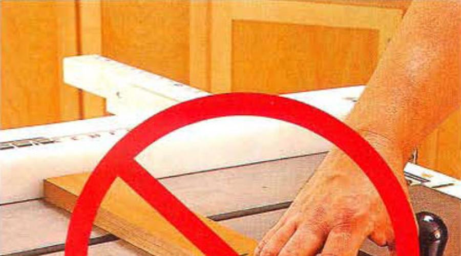
Don't take risks. Every time your hand comes closer than 15 cm to the saw blade, an alarm should go off inside you. Keep pushers handy and always use them to finish cutting when there is a risk that your fingers may be in the danger zone.
22
Always use a rip fence or crosscut fence, but not both at the same time. Never do two things: do not try to cut by guiding the workpiece with your hands, without using a parallel or miter fence, and do not use both stops at the same time. In both cases, there is a high chance that the saw blade will get stuck in the workpiece and throw it straight at you.
23

Use clamps. The spring-loaded rake plates hold the workpiece securely against the rip fence, allowing you to focus on consistent feed rates. Install the clamp so that its tip is in front of the saw blade, as shown in the photo. This will prevent the cut piece from being caught and kicked off.
THE SIMPLEST DEVICES FOR FIXING WORKPIECES
The workpiece installed on the milling machine must occupy a certain position in relation to the milling cutter. Precision of machining and the relative position of the machined surfaces depend primarily on the installation of the workpiece. In addition, the workpiece must be firmly and securely fastened.
It should be remembered that when milling, the cutter tooth presses on the workpiece and squeezes it out. In some cases, the cutter can pick up the workpiece, as a result of which the teeth of the cutter can break, and sometimes an accident with the worker is possible. Inaccuracy, negligence and incorrect installation often lead to marriage.
In the simplest case, the workpiece is fixed directly on the machine table. This is possible when the workpiece has a good support surface. When properly fastened, the workpiece should be in close contact with the table plane with the supporting surface. The machine table usually has three longitudinal grooves into which fixing bolts are inserted. To fasten the workpiece to the table, use clamps, which are pressed with bolts.
Round blanks are installed and fixed in prisms, which in turn are bolted to the machine table.
In tooling (in the manufacture of taps, reamers, end mills), the workpiece is fixed between the centers of the dividing head and the tailstock. Often the workpiece is clamped in the dividing head spindle itself. They also use fastening in a chuck, which is put on the dividing head spindle.
A widespread method of fixing the workpiece is clamping in a machine vise. This attachment is found in many milling applications. When it is necessary to mill the same workpieces in large quantities, special milling devices are used, which ensure greater accuracy of installation and processing, as well as reduce the time for setting and clamping the workpieces.
§ 13. FIXING BLOCKS ON THE MACHINE TABLE
Fixing devices
To fix the workpiece directly on the machine table, use clamps with bolts and clamps.
In fig. 60 shows the different types of clamps. Grip I is the most common. Hole 1
for the bolt it is made oblong, which makes it possible to move the clamp relative to the workpiece to be fixed. Such holes are made in all the clamps shown in fig. 60. Screw 2
at the grip II serves instead of a lining under the grip. Ledge 3
at the grip III as well as the ledge 5
at the grip IV make it possible to use clamps without backing. Ledge 4
grip III lays down on the part. Have a stick IV chamfered 6
so that it does not interfere with the work of the cutter when machining the corresponding surfaces of the workpieces.

Often it is necessary to use a clamp with an extended end (clamps V, VI and Vii). The ends 7, 8
and 9
such clamps are usually inserted into the dimples or rest on the protrusions of the workpiece. By gripping VIII can be used without padding.
Grip IX It is convenient in cases where there are depressions or recesses in the workpiece, where the stuck is introduced by the protrusion 10. Very convenient easy-to-manufacture grip X... To remove it, you do not need to completely roll up the nut, but it is enough to loosen the mold and move the clamp to the side.
In fig. 60, XI shows the clamping of the workpiece 15
grip 12
, which rests on the workpiece at one end 15
, and others - on the lining 11
... Bolt 14
, flat head which enters the T-shaped groove of the table, passes through the clamp. Wrenching the nut 13
, press the clamp to the lining and so fix the workpiece.
Various bars and other parts suitable in height are used as pads for the tacks.
The clamp shown in fig. 60, XII... Rearranging the arcuate grip 16
, having an oblong hole in the center, they are pressed against workpieces of various heights.
The same height-adjustable clamp is shown in Fig. 60, XIII... The lining of the grip is made in the form of a round disc 17
rotating on an eccentrically located axis 18
passing through the slot of the stuck 19
... In disk 17
six holes drilled. Depending on the required installation height, a pin is installed in a particular hole 21
on which the grip rests 19
... Thus, the clamp has three supports: the axle 18
, pin 21
and clamping part 20
... In fig. 60, XIV the grip is shown in the lowest fastening position. The workpiece is clamped with a bolt like the clamp in fig. 60, XI.
Some workpieces can be held securely with clamps. In fig. 61 shows the clamp 4
, the lower end of which 6
enters the T-slot of the machine table. Support jaw 1
has the same bottom end 6
entering the table groove. Clamped workpieces 2
clamped with a bolt 5
pressing the movable jaw 3
... Bolt 5
has a slope for better clamping of the workpiece.
COMMITTEE OF STANDARDIZATION AND METROLOGY OF THE USSR
Moscow
STATE STANDARD OF THE UNION OF SSR
Date of introduction 01.01.93
This standard specifies the dimensions and spacing of T-slots used in tables of machine tools.
The requirements of this standard are mandatory, with the exception of clauses 4, 6, 10.
1. The dimensions of the T-shaped grooves must correspond to those indicated in the drawing. 1 and in table. 1.
Table 1
|
Prev off |
Prev off |
|||||||||
An example of a symbol for a T-shaped guide groove with a width a= 18 mm and H8 tolerance field:
2. Dimension Tolerance a for guide grooves - H8, for clamping grooves - H12.
3. Roughness parameter Ra according to GOST 2789 of the side surfaces, determined by the size a, should be no more than 6.3 microns, other surfaces should not be more than 20 microns.
4. Allowed instead of chamfers e, f and g round the corner with a radius not exceeding the dimensions of the chamfers.
5. The distances between the T-shaped grooves, depending on the width of the grooves, must correspond to those indicated in Fig. 2 and in table. 2.
table 2
|
a |
|||
|
(80); 100; 125; 160 |
|||
|
100; 125; 160; 200 |
|||
|
125; 160; 200; 250 |
|||
|
160; 200; 250; 320 |
|||
|
(40); 50; 63; 80 |
200; 250; 320; 400 |
||
|
(50); 63; 80; 100 |
250; 320; 400; 500 |
||
|
(63); 80; 100; 125 |
Note. Size Values t, those enclosed in parentheses are non-preferred.
6. It is allowed to use smaller and larger sizes. t in comparison with those indicated in the table. 2, which are selected from the Ra 10 range, as well as intermediate values from the Ra 20 range according to GOST 6636.
7. Values of limit deviations of size t must correspond to those indicated in table. 3.
Table 3
Note. The maximum deviation of the distance of any T-shaped groove is not cumulative.
8. With an odd number of T-slots, their symmetrical arrangement with respect to the guide slot should be preferred.
In the case of an asymmetric arrangement of the T-shaped grooves relative to the guide groove, as well as with an even number of grooves, the guide groove must be clearly marked.
9. Design and dimensions of bolts for T-shaped slots - in accordance with GOST 13152.
10. It is allowed to replace the bolted connection with any other device that meets the requirements of interchangeability.
INFORMATION DATA
1 ... DEVELOPED AND INTRODUCED by the Technical Committee for Standardization "Machines" (TC 70 "Machines")
DEVELOPERS
A.N. Baikov, Cand. tech. sciences; Yu.A. Arkhipov, S.S. Kedrov, Cand. tech. sciences; T.V. Dmitrichenkova
2 ... APPROVED AND PUT INTO EFFECT by the Decree of the Committee for Standardization and Metrology of the USSR No. 1514 dated September 27, 1991
3 ... Inspection period - 1998, inspection frequency - 5 years
4 ... The standard complies with the international standard ISO 299-87 in terms of the dimensions of the machined T-shaped grooves
6 ... REFERENCE REGULATORY TECHNICAL DOCUMENTS
A milling table will make your work easier and help to increase the accuracy of workpieces. You can buy a ready-made one, or you can make a milling table for a hand router with your own hands, using the skills of working with wood. We have prepared quite detailed for you step by step instructions for making a table.
The essence of all structures of a horizontal milling table is the same, the idea is clear - you need to think it over for yourself and execute it, taking into account your capabilities. And in the end, get a machine that allows you to process workpieces much more accurately and perform operations that previously seemed difficult for a hand mill.
Decide on the size of the work surface, starting from the dimensions of the workpieces to be processed and the free space in the workshop. Start small - build a simple countertop with upgrade options. Work on it and refine it little by little.
Make a countertop
The simplest table for a router is a separate work plate placed on the joinery gantries or between the pedestals. The device costs pennies and is manufactured in a few hours, but it will allow you to perform a significant proportion of the same operations as a multifunctional machine. You only need MDF or birch plywood with a thickness of 19-25 mm. A plastic-covered panel is better suited, which provides less frictional resistance, and the plate laminated on both sides will not warp during operation.
Set the exact right angle of the cut on the circular saw, cut the parts to size and grind the ends.
 Cutting scheme: 1 - base plate; 2 - stop base; 3 - front wall of the stop; 4 - kerchief (4 pieces, dimensions for 19 mm plywood); 5 - tsar (2 pcs.); 6 - side bar; 7 - connecting strip (4 pcs.)
Advice. Measure the thickness before cutting sheet material which often differs from the standard. Make corrections to the drawings, eliminating problems in the assembly of the structure.
Remove the plastic pad from the sole of the router.

Draw a line in the middle of the slab and place a mark 235 mm from the edge.

Position the overlay so that the router's main adjusters are then closer to the edge of the table. Visually align the center of the lining with the marked point and mark the locations for drilling the holes for the fastening screws.
Determine the center position for the sole with equidistant screws.

For a base with asymmetrically spaced screws, measure the diameter of the pad and the distance from the outer circumference to the edge of the sole.

Draw a line with a pencil in the middle of the beveled side, calculate the distance from it to the center:
- S = D / 2 - (D - H)
Position the cut perpendicular to the midline and mark the center of the sole.

Mark the locations of the mounting screws.

Drill the mounting holes and for the cutter, countersink the recesses. Mark semicircular cutouts in the base and front wall of the stop.

Saw out the bends with a jigsaw. Make frequent auxiliary cuts perpendicular to the edge of the part, just below the scribe line. Then move the file a little closer to the contour line - the pieces will fall out without interfering with the movement of the canvas. Sand the cutout with a sandpaper wrapped around the pipe.
Attach the connecting strips to the bottom of the worktop.

Glue all the blanks and fasten them with additional screws. Select the screws longer than the standard ones by the thickness of the plywood and install the router from the bottom of the plate.
 1 - side plate for fastening with clamps on the gantry; 2 - king; 3 - countersunk guide holes; 4 - front wall of the stop; 5 - self-tapping screw with countersunk head 4.5x42; 6 - kerchief; 7 - the base of the stop
Fix the table on the trestle with clamps, fix the position of the stop with clamps and get to work.
Make a solid base
The worktop can be installed on a frame that is low enough to accommodate the router. The portable table is stored on a rack, and for work is fixed on a workbench. If you milling a lot and there is a lot of free space in the workshop, add support stands to the worktop and you have a complete machine.
Saw out the cabinet elements according to the dimensions given for a table height of 820 mm, or modify them so that the level of the table top is on par with other equipment.
 Frame details: 1 - outer side panel; 2 - inner panel; 3 - back panel; 4 - base
Place the countertop with the back facing up. Install the side panels in sequence and fasten them with screws, pre-drilling the pilot holes. Secure the base, fold the frame with the front side down, line up the square corners and install the two rear panels.
Finally, attach the wheel supports to the bottom of the body with roofing screws... Place the wheel mounting pads at least 20 mm from the edges.
 1 - side stand; 2 - wheel support; 3 - bottom; 4 - inner rack; 5 - back panel
Use the free space in the drawer units to solve the problem of storing tools and supplies.
Embed the mounting plate
Get more overhang of the cutter by placing the tool on a 4-6 mm thick plate made of duralumin, getinax or monolithic polycarbonate.
Cut a square with a side of 300 mm from a sheet, put it on a workbench. Glue the plastic sole of the router on top with double-sided tape, placing it face up in the middle. With a drill of the same diameter as the mounting screws, drill holes in the plate using the plastic pad as a template. Remove the sole, make a recess for the caps with a countersink or a large drill.
Screw the plate to the disconnected router, insert an 8mm drill into the collet. Lower the tool body until the drill touches the surface and rotate the chuck, marking the center. Unscrew the plate and make a hole at the mark with a hole saw.

Place the plate on the countertop and outline the outline. Draw and cut a cutout by inserting the jigsaw blade through the drilled hole. Trim the ends with a file and sand them.

Fix the thin planks around the marked contour with clamps.

Clamp a copying cutter with a bearing in the collet, set the milling depth according to the thickness of the mounting plate. Route in several passes, then add 0.5 mm with the router micrometer and complete the final pass.
Drill the through holes for the screws and expand them on the back of the tabletop with an 11 mm drill for the self-locking nuts. Clean the surfaces and install the nuts on the epoxy, aligning with the screwed in bolts.

Fit the mounting plate to the cutout, place it in place, drill the mounting holes and countersink from the front. Attach the part to the base of the router, insert the tool into the table top and tighten the screws. Check that the plate is flush with the plane of the table top, if necessary, compensate for any errors with washers.
Improve the emphasis
For a faster and more convenient machine set-up, modify the parallel side stop and complement the machine with a pivot stop to help machine the ends of narrow parts. The latter can be taken from a stationary circular saw. Cut aluminum T-rails into the surface of the plate. To make cutouts in the worktop, use a router or circular saw with slot disc.

Lightly round off the top corners of the grooves with sandpaper. Cut the profile to size, drill holes according to the diameter of the screws, process them with a countersink. Insert the parts into the grooves, make thin holes and tighten the countersunk screws.
Drill 7mm holes in the base of the stop, pick up the hex head bolts and plastic handwheels with nuts.

Install the guide profile in the front plate of the stop to secure the hold-downs, auxiliary pads and guards.


Cut out a cover from plywood with a hole in the center, fix it on the gussets located near the cutout of the longitudinal stop. Connect the adapter nipple and connect the vacuum cleaner when working on the milling table.

Add a guard made of plywood trim and a strip of plexiglass to the stop.

To make oblong cuts, drill 7mm holes at the indicated points, connect them with tangents, and make cuts with a jigsaw.
Make homemade clamps and clamps required for milling small items.

The press-comb can be made from maple wood by selecting a straight grain area. Perform the slots between the ridges on a circular machine:
- Set the cutting height to 50 mm.
- Set the cutting width to 2 mm.
- Make a cut.
- Push the workpiece back with the hand pusher.
- Turn the board 180 °, saw through on the other side.
- Move the stop by 5 mm, repeat the operations.
- Move the stop again and make cuts throughout the workpiece.
Secure the clips to the rail with bolts and wing nuts.
 1 - stopper; 2 - clamp-comb; 3 - protective shield; 4 - aluminum guide; 5 - a branch pipe for a vacuum cleaner
Grind the surfaces of the parts, especially where the workpieces will pass during the milling process. Clean the machine from dust and coat with oil.
 1 - a drawer for cutters; 2 - trapezoidal groove for an emphasis
Let's summarize the project
Materials needed:
- Plywood 19x1525x1525 mm - 2 sheets.
- Plastic 4x30x30 mm.
- Several dozen screws.
- Aluminum guides - 2.3 m.
- Wheel support with brake - 4 pcs.
- Carpentry and epoxy glue.
- M6 bolts with nuts.
The ability to take your time and think over each step came in handy, to accurately mark and cut out the blanks, or the desire to learn this. The result is a solid milling table for little money. In the future, you should think about equipping the machine with a switch and a mechanism for adjusting the milling height.
If you set yourself a goal and assemble a milling machine with your own hands, then you can get at your disposal an effective device that allows you to perform many technological operations on metal and other materials. Serial models of such equipment have been well known for a long time; they are actively used in most manufacturing enterprises operating in various industries. Such machines are distinguished by a wide functionality that allows them to process workpieces made of metal, wood and a number of other materials with their help.
Knowing about all the advantages of such a device, many home craftsmen are wondering how, using affordable and inexpensive components. It should be said right away that it is possible to make such a machine, moreover, you can additionally endow it with functions that are inherent not only in milling equipment, but also in turning equipment.
The simplest in execution is a vertical milling machine. You can assemble it on the basis of a hand drill, spending very little time and effort on it. In order to make a more functional mini-milling machine for your home workshop with your own hands, you must find other components and have a lot of time, but such a task is quite solvable.
If you are going to make a milling machine for metal and wood with your own hands, it is very important to pay attention to the fact that the device should work according to the same principle as serial equipment. To keep it important requirement, you can see the drawings of the serial equipment and watch a video of the process of the factory machine.

Milling tables are often called milling machines, but their designs are fundamentally different.
A milling machine is often called a milling table. We will consider its device at the end of this article. But a separate detailed article is devoted to the manufacture of a homemade milling table, which can be found by clicking on the link below.
Tasks of milling equipment
For those who often work in their home workshop, it is often necessary to process various products made of wood and metal. Not all operations with such products can be performed with only hand tools; this often requires special equipment. Of course, you can contact the workshop, but you will need to pay for the services rendered by it.
It is in such situations that a home milling machine can help out, which is quite within the power of every person who knows how to work with his hands. Having become the owner of such equipment, it will be possible to process workpieces of both metal and wood on it. Depending on the availability of certain components at your disposal, you can make both the simplest home-made milling machine for metal, or a more complex device that already belongs to the turning and milling category.

As mentioned above, the simplest mini-machine is assembled on the basis of a conventional drill. The principle of operation of such equipment is similar to that of serial machines of this type. Although functionality a mini-machine made on the basis of a drill is somewhat more modest than that of more complex home-made equipment, and there will always be a use for such a device in any home workshop.
In order to make a more functional and complex desktop machine with your own hands, you will need a powerful electric motor, as well as a whole list of specific components. Such a machine, assembled according to all the rules, will allow you to perform rather complex technological operations in the conditions of your home: cut out products of complex configuration from metal and wood, process curved surfaces, choose grooves, folds, splines, and much more.
Before making a milling machine with your own hands, you should study the principle of operation of serial equipment, watch a video of its operation, draw up a drawing, prepare the mandatory components and tools that will be needed to assemble your home machine.
Homemade milling machine: option number 1

Base Stand parts and spindle holder Vertical rail (sled) Vertical rail (rear view)
Connecting the base to the column Connecting the base to the column (rear view) Fasten the vertical rail to the column X-ray table G5757 "Proma" is installed on the base
Lead screw of the coordinate table Platform for fastening the spindle (selected by the milling cutter) Base with a stand, guide and table A pair of weights from the beam balance provided the spindle overhang
Vise Motor mount Motor mount (side view) Drive belt
Homemade milling machine: option number 2
Homemade or manual frezer with self-made mechanisms for feeding the cutter and moving the working table. Below in the video, the stages of manufacturing with an analysis of key elements. Namely: rack assembly, vertical rack carriage design, machine table drive.

The author explains the manufacturing process, which would later become a milling machine.
Analysis of the creation of the cutter feed system, as well as the attachment of the cutter (or drill) to the machine stand with the possibility of changing the tool.
Disassembly of the coordinate table drive to ensure the possibility of moving the workpiece relative to the cutter.
Equipment design and operation
If you look at the drawing of a professional, you will notice that its design includes many different mechanisms and assemblies. The desktop home machine, in contrast to the serial one, has a simpler design, consisting of a limited set of required elements. Despite the simplicity of the system, a home-made milling machine is a fairly functional device and allows you to successfully solve many problems associated with the processing of metal and wood blanks.

One of the options for a homemade milling machine. The lack of an insufficiently developed drill mount, but from here you can borrow the design of the bed
The basis of any such machine is the bed, which must be rigid and reliable in order to be able to withstand the required loads. The next important element homemade machine the milling group is a drive, the rotation from which will be transmitted to the working tool. As such a drive, you can use a hand drill or a separate electric motor with a sufficiently high power.
To place and fix the workpieces that will be processed on such equipment, its design must necessarily include a working table with fasteners for the processed parts. Processing on both professional and home milling equipment is carried out using a special tool - a cutter with a sharpened working part.

When making a mini-machine for the home, you should not save on components. They should only be of high quality, as this directly affects the reliability and performance of your equipment.
The technical characteristics that your home bench machine will acquire will depend on a number of parameters. These include the dimensions of the desktop, as well as the permissible weight and dimensions of the workpieces that will be placed on it. An important factor affecting the performance and power of the equipment is the power of the drive installed on it and the maximum number of revolutions that it can provide.

Another option for a homemade milling machine
Milling table assembly process
You should start assembling a homemade machine for your home with the manufacture of a desktop - the most important structural part of milling equipment. The desktop of a home machine can be made with your own hands from a sheet of plywood, plexiglass or sheet metal.
For consumables, you will need high-quality contact adhesive, double-sided tape, and a lot of sandpaper. In addition, it will be necessary to purchase several clamps, hardware and a high-quality copy router, which must be characterized by maximum accuracy and have a sharp cutting surface. The technical capabilities of your desktop machine will largely depend on how high-quality milling cutter you purchase.

Drawing of a milling machine made by the type of a milling table (click to enlarge)
To make milling equipment with your own hands, use the following instructions.
- The first step in assembling a homemade machine is to make a cover. You can use plywood as a material for it. The simple process of manufacturing this element is as follows: blanks of certain sizes are cut from plywood, then they are connected to each other.
- The next stage in assembling a home mini-machine is the installation of fasteners, installation of a router and other structural parts. Since you are engaged in the manufacture of milling equipment, all work should be performed with increased accuracy and precision.
- After assembling the desktop, you need to install the mounting plate on it. For this purpose, a recess is made in the surface of the desktop, the contours of which completely repeat the shape of the mounting plate. In such a recess, the mounting plate is fixed with double-sided tape. Further, along the entire contour of the plate with a certain step, gaskets are laid, which are pressed against it with the help of clamps.
- The working body of the machine itself - a copy milling cutter - is installed in bearing assemblies, the assembly of which should be given special attention.
- All technological holes required on the surface of the worktable can be obtained using a conventional hand drill.
- Your mini bench-top machine will have a row of wood surfaces that need to be carefully sanded with sandpaper.
- The next stage in the manufacture of a homemade machine is the assembly of the base, which must be carried out in strict accordance with a previously prepared drawing.
- When assembling the machine, special attention should be paid to the process of mounting the stop and the clamping comb.
